
As described elsewhere, I've now got my music collection ripped onto a server PC. A new problem then became apparent: when the phone rang, I had to find (a) the remote for the Squeezebox to pause it, and then (b) the phone to read the incoming number and see who's calling. When making a call, we needed to pause the Squeezebox first. In both cases, we needed to remember to unpause the music again afterwards. Surely technology could help here — what I wanted was a system which would do a few things:
I've put a system together which sits between the phone line and the SlimServer and achieves the above.
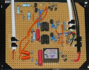
This is pretty much just three circuits grabbed from the web cobbled together in parallel. (See the end of this page for links to the circuits used.) The bottom part of the board in this picture is the audio part, which is fed to the microphone input on the computer's sound card. The other two detect ring signal and whether the phone is off-hook, and feed these to the RI and DSR signals of the serial port. Everything is electrically isolated; the audio part through a transformer taken from an old modem, and the digital parts through opto-isolators. The whole circuit presents a very high impendance to the line (including very high DC resistance) so as not to disturb normal operation.
I made a couple of tiny changes to the circuits I found, such
as fiddling with the capacitor values until each individual
ring of the ring ring ... ring ring ... ring ring
generated its own pulse, but essentially there wasn't anything
too tricky to do here.
Caller-id information is presented as an electrical signal on the pair of copper wires making up the phone line after being translated down through a number of layers of abstraction. Before getting to how to go backwards from the voltage signal on the phone line to the message, an explanation of how the message gets turned into a voltage signal:
At the uppermost level, the message is of the form
Call setup:
        Date and time: 29 April, 18:34
   Calling party's ID: 0871231234
i.e, a collection of values for different parameters. The first step is to turn this into a sequence of octets:
The message gets turned into an octet stream according to the details in standard ETS 300 659-1, available free of charge from the ETSI website after a not-too-annoying registration step. Each parameter is encoded in the form [type], [length], [value], and the whole lot is then wrapped with a header at the front and a checksum at the back.
The example message above becomes (with all octets written as hex):
80                              message type; "Call setup"
16                              message length; 0x16 == 22 octets, excl. framing
01                              parameter type; "date/time"
08                              parameter length; 8 octets to follow
30 34 32 39 31 38 33 34         parameter value; "04291834" in ASCII
02                              parameter type; "calling party ID"
0a                              parameter length; 10 octets to follow
30 38 37 31 32 33 31 32 33 34   calling ID; "0871231234" in ASCII
b7                              checksum
The octet sequence is then turned into a bitstream:
Each octet is framed by a start bit (always 0) and a stop bit (always 1). Each octet's bits are transmitted least-significant bit first. The whole lot is then prefaced with a "channel seizure signal" (alternating 1s and 0s) and a stream of "mark"s (bits with value 1), and followed by a handful of mark bits. The example now looks like, with the bits transmitted in the order they're written here:
010101...010101   "channel seizure", 300 bits altogether
111111...111111   "mark signal", 55--105 bits altogether
0 00000001 1      0x80 == 10000000 (binary)
0 01101000 1      0x16 == 00010110 (binary)
...
0 11101101 1      0xb7 == 10110111 (binary)
1111              trailing marks
The last step is to turn the stream of 1s and 0s into a signal:
The modulation used is 1200-baud V.23 frequency-shift keying. A "0" ("space") is transmitted as (1/1200)s (0.83ms) of 2100Hz, and a "1" ("mark") as (1/1200)s of 1300Hz. The phase of each symbol's signal is arranged so that the signal is continuous in time. For example, together with its start and stop bits, an ASCII "5" character (0x35, bit-sequence 0101011001) looks like this:
Well, that's the synthesised version. In reality, a randomly-chosen snippet of the signal once it's been captured looks more like this:
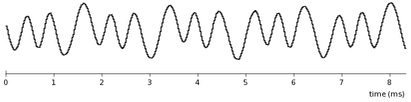
Note the different amplitudes of the mark and space tones, and the jagged appearance caused by sampling at 48kHz. The question now is how to get from this signal back up through the layers to the message "received call from 0871231234 at 18:34 on 29 April".
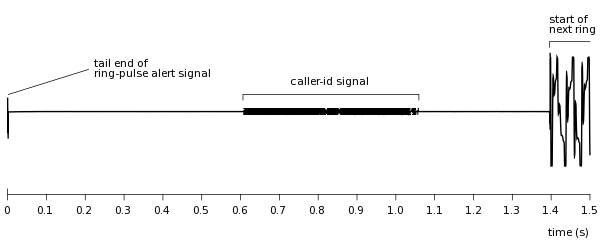
Working back up, the first thing to do is turn the signal into a stream of 1s and 0s. I first capture the signal using the microphone input of the sound card, triggered by the arrival of the Ring-Pulse Alert Signal. This gives me 1.5s of sound, recorded at 48000Hz mono:
The first step is to filter out frequencies which are outside the 1300Hz--2100Hz range, as they are noise as far as the caller-id signal is concerned. We've now got quite a clean signal, and can pick out the burst of v23 information by a threshold on the RMS signal, over 1ms windows. There is still some signal by the ringing pulses, because they are of very large amplitude, and the filter doesn't get rid of them completely. Nonetheless, we can pick out just the cid signal:
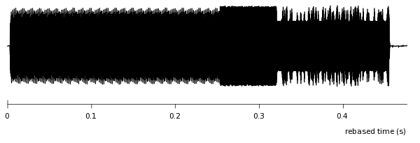
The aliasing of this graph means that you can see the channel-seizure signal, followed by the mark burst, followed by the actual information. The information-bearing part of the signal is a bit less than one third of the whole.
The next step is to use a property of the cosine wave when multiplied by a time-shifted copy of itself: cos(A)cos(B)=[cos(A-B) + cos(A+B)]/2, and in our case A=wt, and B=w(t-d):
cos(wt) cos(w(t - d)) = [ cos(wd) + cos(2wt - wd) ] / 2
I.e., we get a sum of two components: a DC shift of cos(wd), and a doubled-frequency component cos(2wt), give or take a phase shift of wd. If we choose the delay d such that cos(wd) is zero at the centre frequency of the two tones, the DC shifts of the mark tone and the space tone will be separated maximally. We also want d to be small enough that the delay doesn't take us back into the previous symbol. We choose d such that wd is pi/2 to satisfy these constraints. For our case, with w=2*pi*1700, this means d=(1/6800)s, or almost exactly 7 samples at 48kHz. The DC shift of the mark tone (1300Hz) is then cos(1300*2*pi/6800)=0.36, and of the space tone (2100Hz), cos(2100*2*pi/6800)=-0.36. The example capture above looks like this when delayed and multiplied (excerpt):
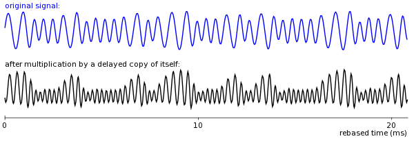
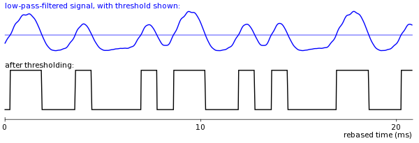
Filtering out the high-frequency part of the multiplied signal should leave us with a signal which is positive where a 1 is being transmitted and negative where a 0 is. A 1200bps signal of alternating 1s and 0s would have a frequency of 600Hz, so we apply a low-pass filter with this cut-off frequency, and get:

The individual 0s and 1s are emerging, although it looks like there's a phase shift caused by the filter. We can find a threshold signal level by examining the channel seizure part of the signal, which is a stream of alternating 1s and 0s. The threshold is just the average of the low-pass-filtered signal during the first 250 bit-times, i.e., 10,000 samples. Classifying the signal as mark or space according to whether it is above or below this threshold respectively gives:
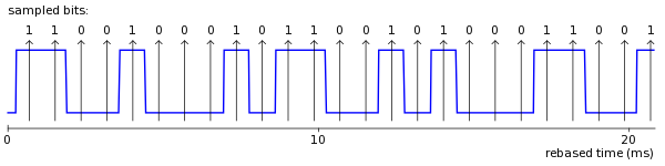
The final stage of recovering the bitstream is to find the phase, so that we can sample the above signal at the mid-point of each bit-time. We start by assuming a phase of zero, and then finding the phase of each bit-transition — this is done by taking the sample number of the transition and finding its remainder after division by 40, the number of samples in a bit-time. These phase numbers should all be roughly the same, although if we're unlucky we might end up with a sequence like 38, 1, 39, 1, 38, 2, 2, ... if we happened to have been close with our original zero-phase estimate. We therefore also start with a phase of 20, and choose the sequence with the smaller variance. We can now sample at the mid-point of each bit and recover the stream of 0s and 1s:
Recovering the bytestream from the bitstream involves searching for the end of the channel seizure signal, then the end of the mark burst, then reading off the bits ten at a time, discarding the start and stop bits, and forming a byte out of the eight that are left. Ideally I would check that the start bit is a 0 and the stop bit a 1, but don't. Another refinement would be to keep track of the phase as I go through the thresholded signal, in case it wanders around, but, again, this didn't turn out to be necessary.
No doubt this could all be done in hardware using half a dozen components, but it's quite pleasing seeing the signal going through the various stages of decoding. Even if using a whole PC to do the job is overdoing it a bit. Out of many hundred CID signals received, the system has only failed to decode one, with a single bit error. There was a bit of a glitch on the line during the signal, and our normal phone also failed to decode this one, so I'm happy with the reliability of the code. I could make it more robust by incorporating the knowledge that a 'u' character in the middle of a phone number is more likely to be a '5' with the 26 bit incorrectly decoded.
Decoding the bytestream into the message is relatively straightforward and gives the original call setup caller-id message.
The SlimServer software has a telnet-style interface which is well suited for this job. I wrote a small extension to the SlimServer software which introduces the notion of an interruption to the music — any music playing is paused, and information is shown on the screen. For frequent callers, a synthesised voice (sound files created using "Audrey" from AT&T's online demo of their Natural Voice product) announces the caller too.
The software running on an old PC (in case I blew up the sound card, the serial port, or both while connecting the circuit to the PC) consists of three processes (monline-d, record-d, and control-d), communicating via SysV message queues Qr and Qc:
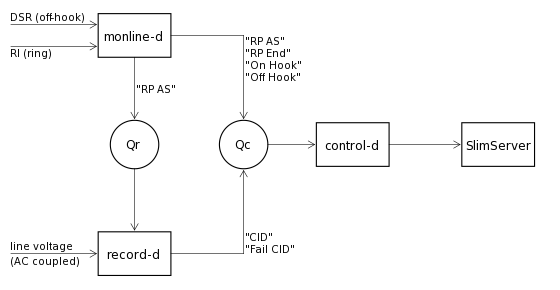
The monline-d process monitors the states of the ring-indicator and on-/off-hook indicator lines coming into the serial port. It notices transitions in their state, and sends messages as appropriate. If the phone has been off-hook for more than 150ms, it sends the "Off hook" message — brief "off-hook" pulses are seen at the end of ring pulses and these should be ignored. As soon as the line goes back on-hook, it sends the "On hook" message. A ring pulse is timed, and if it falls within the bounds allowed for a Ring Pulse Alert Signal, it send two "RP AS" messages — one to record-d, and one to control-d. At the end of a ring pulse longer than 350ms, it sends the "RP End" message. Ring pulses shorter than 150ms are ignored as glitches.
record-d listens for a "RP AS" message from monline-d. When it receives one, it records the next 1.5s of audio from the line, and performs the processing described above. If it successfully decodes the caller-id, it sends a "CID" message including the phone number of the caller. If it fails, e.g., because of bad checksum, it sends a "Fail CID" message. In practice, if we pick up the phone at just the right time part-way through a ring, monline-d thinks it's a RPAS and then record-d gets garbage. This problem is handled within control-d. The record-d program is written in C because of the time-sensitive nature of its job. It decodes the caller-id signal in around 20ms on the slow old PC. While testing the algorithm, though, I used Python.
Finally, control-d works out what is going on from the stream of messages sent by monline-d and record-d. It is almost a state machine but has a couple of hacks in it. It then talks via a TCP connection to the SlimServer software running on the main server machine, and tells it to pause the music, triggers the announcements so they are made between the actual "ring ring"s of the incoming call, unpauses the music when the call is over, etc. The telephone-line PC is on the whole time, whereas the SlimServer PC is not, so control-d also has to deal with fiddly details like not falling over when its connection to the SlimServer is terminated.
The system works pretty much as designed. There are a couple of tiny bugs left, such as the "shuffle" status of the playlist not being preserved by my patch to the SlimServer software, but by and large it works and is surprisingly useful. It is very cool to hear [music music music] ring [music stops] ... ring ring ... "Ben's work" ... ring ring ... "Ben's work" ... etc.
Since I have the ability to record the phone line at any time, there are a couple of things it would be cool to have:
If I could inject audio into the phone line as well as record audio from the phone line, fixed-line SMS would be a neat hack.
For the telephone interface circuitry:
For constructing the filters used in decoding the FSK:
Can't remember where I read about the technique of multiplying the signal by a 90-degree lagged copy of itself.
(Address as image to foil spam-harvesters, sorry.)
![]()