Remote display for pinball machine
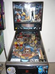
We have a very cool Twilight Zone pinball machine in our garage. I bought it over twenty years ago while I was a student, and with a bit of attention, it’s provided lots of fun since then.
My son, Zach, now 9, has been getting steadily better at it [2018-01-28: see update at end], and is keen for me to watch his games. So he and I wanted a way for me to keep an eye on how his game is going, while I do other jobs elsewhere. We decided to make a system to transmit the pinball machine’s dot-matrix display to a desktop or laptop.
Thanks to the drawing skills of my eldest, Marlowe, this cartoon gives the idea of what we were trying to achieve:
One way to do this would be to set up a webcam. But where’s the fun in that? Instead, I suggested we work out how to eavesdrop on the communication between the pinball machine’s display driver board and the actual display, and reconstruct the images.
Initial research
A bit of internet research turned up some useful information on how the images are sent by the driver board to the display:
- Others have studied and described the logic of the display and its driver board. A “Pinball Rehab page” had a section ‘DMC Theory’, but I can no longer [as of 2023-04-20] find it on the web.
- The Free-WPC project describes the theory of operation in section A7.
- The WPC schematics manual has the display circuitry on what are labelled pp.6–9 (pp.8–11 of the PDF).
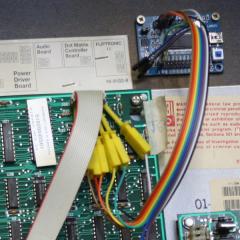
To check we could see what we expected to see, I bought a 16-channel USB logic analyzer [see update below], and Zach and I clipped it to the relevant pins of the ribbon cable connectors at the top right of the backbox:
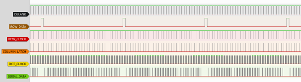
Connecting this rather precarious arrangement to a laptop running the free-software sigrok suite let us capture some example traces at 4MHz:
[Update 2019-07-01: The particular logic analyzer we used has since been discontinued. The same company are now offering what looks like a better-packaged variant of the same design, although I haven’t tested it. I also imagine that any bare-board design based on the same chip (Cypress FX2LP CY7C68013A) would do the job; these are easy to find on eBay. Check for sigrok compatibility.]
Exploring in more detail confirmed that the data looked reasonable. We could see well-distinguished frames and rows, and within each row, the pixel data had a mixture of high (lit pixel) and low (dark pixel). There were also a couple of other features of interest; see details at end of post.
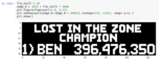
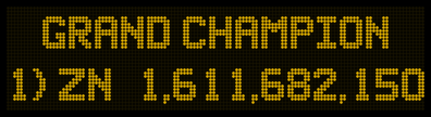
The next step was to experiment with recovering a display frame from the signals, using a Jupyter notebook. This was pleasingly straightforward, and also successful. By an amazing coincidence, the frame I decoded was one showing that I am the current Lost In The Zone champion.
How to proceed from here?
At this stage we were pretty confident we’d be able to get the whole thing to work, one way or another. But it wasn’t clear exactly how.
- Custom hardware? I had originally imagined we might need to build some custom logic hardware to capture the pixels, and then allow a host machine to read them out with a one-frame lag.
- Pure software reading logic analyzer data? However, given that the logic analyzer was successful, it looked like it would be worth a try to just do the whole thing in software, maybe even on a Raspberry Pi. The newer models are pretty powerful, especially in the context of this simple-seeming task.
Move to embedded Raspberry Pi
I had a couple of concerns about using a Raspberry Pi for this real-time task:
- Would its CPU be able to keep up? It would have to do the decoding of the pinball-machine signals, as well as encode into video and transmit.
- Continuous capture from the logic analyzer might not leave much room for manoeuver when it comes to USB bandwidth and latency, especially as the Raspberry Pi’s ethernet interface is internally connected over USB.
A mock-up script of running the logic-analyzer capture, and transmitting placeholder data over UDP ran without dropping either logic-analyzer data or ethernet packets, so I was sufficiently encouraged to continue with this.
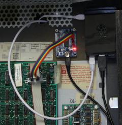
The hardware side was easy enough; by now we’d graduated to a proper crimp-on connector to tap off the ribbon cable (see photo). The Raspberry Pi is in the black case at top-right of the photo.
I guessed that Python wouldn’t keep up in real time, so re-wrote the prototype Jupyter script into C++. I talked through with Zach what the program needed to do — detect clock edges, sample pixel data, collect rows, etc. — but then he left me to do ‘all the boring typing’.
For live and continuous running there are a couple of extra details to take care of; details below.
Video encoding, transmission, and reception
After researching a few alternatives, I found several success reports of people using the ‘open source multimedia framework’ gstreamer for transmission and reception of a live video stream with a Raspberry Pi, so decided to try it. An initial version worked pretty well, but it’s an important part of the aesthetic of the video art that the display is made up of small orange dots, so I inserted an ‘expand into dots’ stage into the ‘receive’ video pipeline.
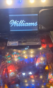
The final result looks pretty good I think:
The video here is reduced and made looping for this post; the full-size version is twice as high and twice as wide. This was captured after the whole encode, transmit, receive, decode pipeline.
Encoding is h264 at 160kbits/sec. You do get a small amount of stuttering sometimes when receiving over WiFi, but it’s very steady on a wired connection. The processes running on the Raspberry Pi (logic analyzer capture, frame decoding, video encoding and transmission) have been running very reliably.
2023: Replication by someone else!
I was contacted in April 2023 by Pinside user Rolpa, who, after some back and forth over email, reported success in getting this all to work on a laptop. Gratifying that it was useful for someone else!
Rolpa also pointed me towards the DMD Extensions project, which looks cool.
Future work
As always, there are some avenues which could be explored further:
- The EZ-USB chip used on the logic analyzer is a pretty capable microprocessor, with built-in support for USB tasks. It ought to be possible to program it to decode the pinball signals into pixels. See its data sheet and technical reference manual.
- It would be very cool if the device could appear as a USB Video Camera.
- Try the other solution of building some hardware to capture into RAM.
- Capture and transmit the sound — the current solution is to turn the pinball machine’s volume up and open the doors.
- Capture the state of the playfield lights, and reconstruct the playfield on the receiver.
- Investigate webRTC properly as an alternative to
gstreamer. - Study the circuit diagram more carefully and understand its operation in conjunction with the observed behaviour.
- Get another Raspberry Pi, with display, to make a dedicated remote display unit.
- Solve a mystery: I can’t successfully launch the Raspberry Pi ‘capture, encode, transmit’ script in the background without losing logic analyzer data. Equally oddly, if I launch it over
sshand then kill the ssh session, the process lives on, and the whole thing seems to work.
Some extra details
Curious features of captured signal
- The form of the dot-clock. The driver clocks 500,000 pixels per second to the display, but not at a steady 500kHz. For every row, the clock line has a 128-cycle burst of 1MHz, followed by a same-length period of low.
- There seems to be noise on the ‘data’ line, mostly in the ‘clock low’ period between display rows, but also glitches during the actual row data. I initially thought the extra loading of the logic analyzer probes might be upsetting the signals, but they do cope with travelling over a couple of feet of ribbon cable flapping around right next to power supply boards so they must be quite robustly-driven.
- It turned out that the greyscale display is achieved by treating the raw frames as being in groups of three, allowing four greyscale levels. The raw frames run at c.122Hz, so we can treat the display instead as a c.41Hz after this grouping.
Live real-time display signal decoding
- Although the pinball machine clocks the pixels at a nominal 8·192ms per frame, and the logic analyzer samples at a nominal 4MHz, these two clocks are not going to be locked together. Therefore the frame-decoder needs to keep a running estimate of how many logic-analyzer samples there are in one display frame.
- When starting from power-on, we have no idea of where we are in the signal, so we need a ‘cold-start’ process to find an initial lock to the frame-start.
- When the pinball machine is switched off, we no longer see the expected signal. The decoder needs to detect this, and switch to emitting a ‘no signal’ sequence. It also then needs to notice when it starts seeing the expected signal again, and recover lock.
- To reduce the demands on the video encoding and tranmission stages, the decoder accumulates six consecutive frames and emits just one seven-level greyscale frame.
Raspberry Pi CPU usage
While running, the various processes running on the Raspberry Pi take up the following amounts of CPU:
- Capture driver for the logic analyzer: 100% of one core
- Frame decoder: 15% of one core
- Video encoding and transmission: 5% of one core
The quad-core Pi therefore is around 70% idle while doing this work.
Source code
It’s very unlikely that the code I wrote will be useful except in this exact situation, but all the same it’s available under the GPLv3 on github.
See also
Other Raspberry Pi project:
Acknowledgements
Thanks to Oliver Nash for the idea of including an overview cartoon.
Update 2018-01-28: New Grand Champion
It had to happen eventually — I got knocked off the high-score slot: